
Description
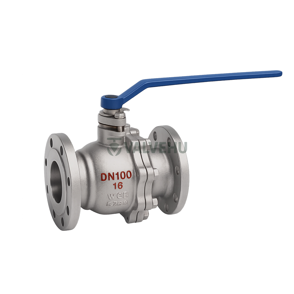
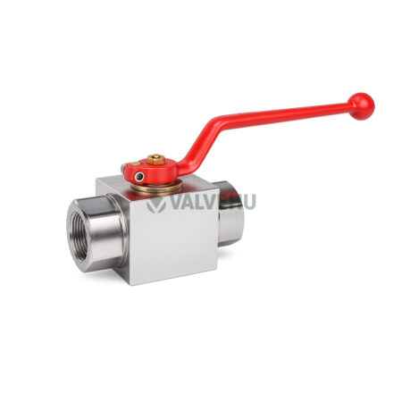
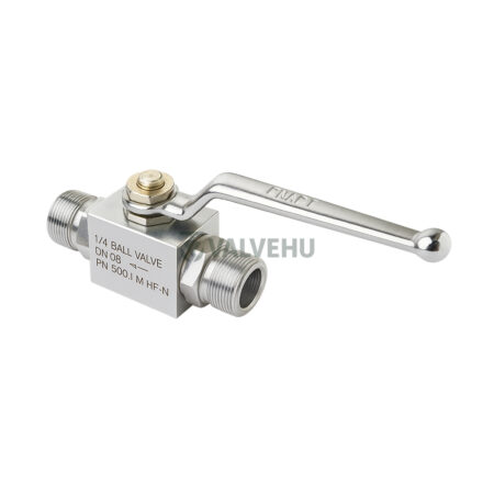
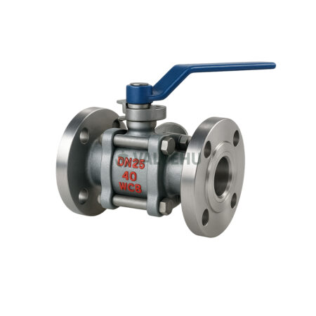
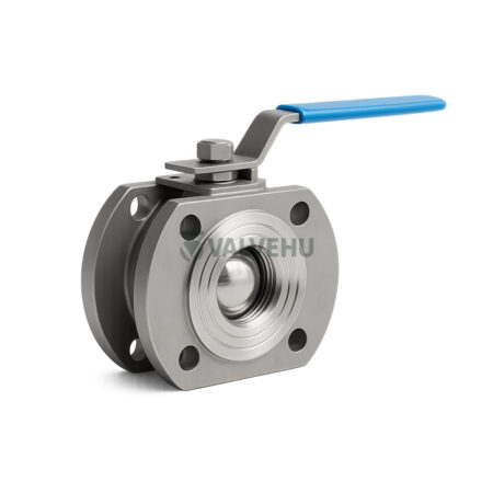
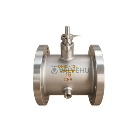
Buy Floating Ball Valve Q41F/H PN1.6/2.5/4.0/6.4/10.0 Stainless Steel Flanged Manual
The VALVEHU Q41F/H Series Floating Ball Valve is a high-performance industrial solution designed for precise flow control and reliable sealing in a wide range of fluid systems. Manufactured under strict compliance with GB/T 12221, ASME B16.10, JB/T79, and API 598 standards, this floating-type valve offers both soft-seated and hard-seated options for superior flexibility across different industrial environments.
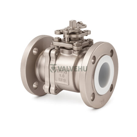
This valve is part of the ball valve family, known for their quarter-turn operation and bubble-tight shutoff capability. The Q41F/H series supports working pressures of PN1.6, PN2.5, PN4.0, and PN6.4 MPa, accommodating applications from low to high pressure. Its body is constructed using premium-grade materials such as A351 CF8M, A351 CF3M, and others, with seat options in PTFE, STL, and graphite, making it suitable for water, steam, oils, weak acids, and acetic media at temperatures from -196°C to 425°C.
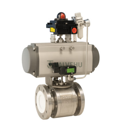
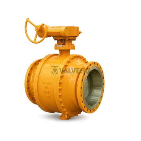
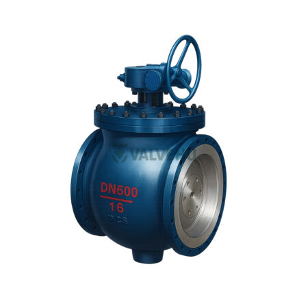
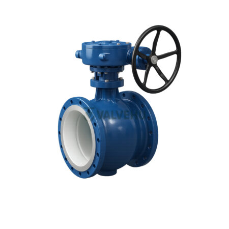
End connections are flanged as per ASME and GB standards, while the valve is operated manually via lever or can be fitted with gear, pneumatic, or electric actuators. The Q41F design also ensures low torque operation and optimal sealing, making it ideal for demanding pipeline systems.
Its robust construction and full-bore passage ensure minimal pressure drop, while the anti-blowout stem design and anti-static features enhance operational safety. Available in a wide DN range (DN15–DN300), this valve is an excellent fit for oil & gas, chemical, steam, and HVAC systems.
For engineers and procurement specialists seeking durable, multi-pressure class valves with reliable sealing performance, the Q41F/H offers proven performance and global standardization. For expert support and sourcing assistance, connect with VALVEHU technical consultants in China. We’re ready to help you find the exact valve you need.
Technical Specifications
Valve Type: Floating Ball Valve
Pressure Ratings: PN1.6 / PN2.5 / PN4.0 / PN6.4 MPa
Body Materials: CF8, CF8M, CF3, CF3M
Seat Materials: PTFE, STL, Graphite
Operating Temp Range: -196°C to 425°C
Applicable Media: Water, Steam, Oil, Acids, Acetic
End Connection: Flanged (ASME/GB Standard)
Valve Size Range: DN15 to DN300
Standards: API 598, ASME B16.10, GB/T 12221
Actuation Options: Manual, Gear, Pneumatic, Electric
Main Component Materials
| Part Name | Material 1 | Material 2 | Material 3 | Material 4 | Material 5 | Material 6 |
|---|---|---|---|---|---|---|
| Body | A351 CF8C | ZG0Cr18Ni10Ti | A351 CF8 | A351 CF8M | A351 CF3 | A351 CF3M |
| Bonnet | A351 CF8C | ZG0Cr18Ni10Ti | A351 CF8 | A351 CF8M | A351 CF3 | A351 CF3M |
| Ball | A182 F347 | A182 F321 | A182 F304 | A182 F316 | A182 F304L | A182 F316L |
| Seat | PTFE/STL | PTFE/STL | PTFE/STL | PTFE/STL | PTFE/STL | PTFE/STL |
| Stem | 0Cr18Ni10Ti | 0Cr18Ni10Ti | 06Cr19Ni10 | 06Cr17Ni12Mo2 | 022Cr19Ni10 | 022Cr17Ni12Mo2 |
| Gasket | PTFE/304 + Graphite | PTFE/304 + Graphite | PTFE/304 + Graphite | PTFE/304 + Graphite | PTFE/304 + Graphite | PTFE/304 + Graphite |
| Stud Bolt | A193 B8 | A193 B8 | A193 B8 | A193 B8M | A193 B8 | A193 B8M |
| Nut | A194 8 | A194 8 | A194 8 | A194 8M | A194 8 | A194 8M |
| Operating Temperature | Soft Seat: -196-250°C Hard Seat: -196-425°C |
Soft Seat: -196-250°C Hard Seat: -196-425°C |
Soft Seat: -196-250°C Hard Seat: -196-425°C |
Soft Seat: -196-250°C Hard Seat: -196-425°C |
Soft Seat: -196-250°C Hard Seat: -196-425°C |
Soft Seat: -196-250°C Hard Seat: -196-425°C |
| Applicable Media | Water, steam, oil, acetic acid types | Water, steam, oil, acetic acid types | Water, steam, oil, acetic acid types | Water, steam, oil, acetic acid types | Water, steam, oil, acetic acid types | Water, steam, oil, acetic acid types |
Main Performance Parameters
| Nominal Pressure PN (MPa) | Shell Test (MPa) | Water Seal Test (MPa) | Upper Seal Test (MPa) | Air Seal Test (MPa) | Applicable Media | Applicable Temperature |
|---|---|---|---|---|---|---|
| 1.6 | 2.4 | 1.76 | 1.76 | 0.5–0.7 | C – Water, Steam, Oil | 150°C |
| 2.5 | 3.75 | 2.75 | 2.75 | 0.5–0.7 | P – Nitric Acid Type | 200°C |
| 4.0 | 6.0 | 4.4 | 4.4 | 0.5–0.7 | R – Acetic Acid Type | 380°C |
| 6.4 | 9.6 | 7.04 | 7.04 | 0.5–0.7 | R – Acetic Acid Type | 380°C |
| 10.0 | 15.0 | 11.0 | 11.0 | 0.5–0.7 | R – Acetic Acid Type | 380°C |
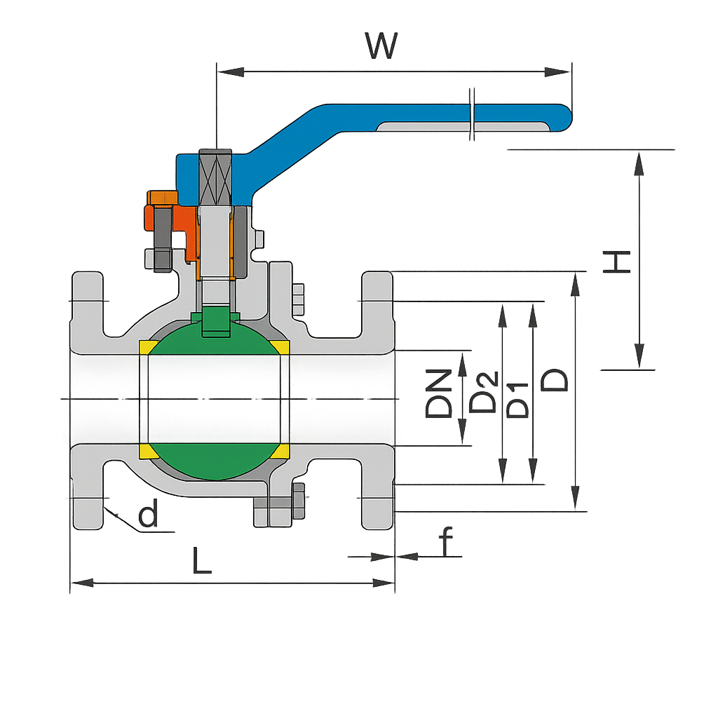
Main Dimensions and Connection Sizes (Unit: mm)
| Nominal Pressure PN(MPa) | Nominal Diameter DN(mm) | L (Series 1) | L (Series 2) | W | H | D | D1 | D2 | b | f | Z–d |
|---|---|---|---|---|---|---|---|---|---|---|---|
| 1.6 | 15 | 130 | 130 | 140 | 59 | 95 | 65 | 45 | 14 | 2 | 4–14 |
| 1.6 | 20 | 140 | 130 | 160 | 63 | 105 | 75 | 55 | 14 | 2 | 4–14 |
| 1.6 | 25 | 150 | 140 | 180 | 75 | 115 | 85 | 65 | 14 | 2 | 4–14 |
| 1.6 | 32 | 165 | 165 | 250 | 85 | 135 | 100 | 78 | 16 | 2 | 4–18 |
| 1.6 | 40 | 180 | 165 | 300 | 95 | 145 | 110 | 85 | 16 | 3 | 4–18 |
| 1.6 | 50 | 200 | 203 | 350 | 107 | 160 | 125 | 100 | 16 | 3 | 4–18 |
| 1.6 | 65 | 220 | 222 | 350 | 142 | 180 | 145 | 120 | 18 | 3 | 4–18 |
| 1.6 | 80 | 250 | 241 | 400 | 152 | 195 | 160 | 135 | 20 | 3 | 8–18 |
| 1.6 | 100 | 280 | 305 | 500 | 178 | 215 | 180 | 155 | 20 | 3 | 8–18 |
| 1.6 | 125 | 320 | 365 | 600 | 252 | 245 | 210 | 185 | 22 | 3 | 8–18 |
| 1.6 | 150 | 360 | 394 | 800 | 272 | 280 | 240 | 210 | 24 | 3 | 8–23 |
| 1.6 | 200 | 457 | 400 | 800 | 342 | 335 | 295 | 265 | 26 | 3 | 12–23 |
| 1.6 | 250 | 533 | 533 | – | 495 | 405 | 355 | 320 | 30 | 3 | 12–25 |
| 1.6 | 300 | 610 | 610 | – | 580 | 460 | 410 | 375 | 30 | 3 | 12–25 |
Main Dimensions and Connection Sizes for Q41F/H, Q341F/H, Q641F/H, Q941F/H (Unit: mm)
| Nominal Pressure PN (MPa) | Nominal Diameter DN (mm) | L (Series 1) | L (Series 2) | W | H | D | D1 | D2 | D6 | b | f | f1 | Z–d |
|---|---|---|---|---|---|---|---|---|---|---|---|---|---|
| 2.5 | 15 | 130 | 130 | 130 | 59 | 95 | 65 | 45 | – | 16 | 2 | – | 4–14 |
| 2.5 | 20 | 140 | 130 | 130 | 63 | 105 | 75 | 55 | – | 16 | 2 | – | 4–14 |
| 2.5 | 25 | 150 | 140 | 160 | 75 | 115 | 85 | 65 | – | 16 | 2 | – | 4–14 |
| 2.5 | 32 | 165 | 165 | 180 | 85 | 135 | 100 | 78 | – | 18 | 2 | – | 4–18 |
| 2.5 | 40 | 180 | 165 | 230 | 95 | 145 | 110 | 85 | – | 18 | 3 | – | 4–18 |
| 2.5 | 50 | 200 | 203 | 230 | 107 | 160 | 125 | 100 | – | 20 | 3 | – | 4–18 |
| 2.5 | 65 | 220 | 222 | 400 | 142 | 180 | 145 | 120 | – | 22 | 3 | – | 8–18 |
| 2.5 | 80 | 250 | 250 | 400 | 152 | 195 | 160 | 135 | – | 22 | 3 | – | 8–18 |
| 2.5 | 100 | 280 | 305 | 700 | 178 | 230 | 190 | 160 | – | 24 | 3 | – | 8–23 |
| 2.5 | 125 | 320 | 356 | 1100 | 252 | 270 | 220 | 188 | – | 28 | 3 | – | 8–25 |
| 2.5 | 150 | 360 | 394 | 1100 | 272 | 300 | 250 | 218 | – | 30 | 3 | – | 8–25 |
| 2.5 | 200 | 400 | 457 | 1500 | 342 | 360 | 310 | 278 | – | 34 | 3 | – | 12–25 |
| 2.5 | 250 | 533 | – | – | 495 | 425 | 370 | 332 | – | 36 | 3 | – | 12–30 |
| 2.5 | 300 | 610 | – | – | 580 | 485 | 430 | 390 | – | 40 | 4 | 4 | 16–30 |
| 4.0 | 15 | 130 | 140 | 130 | 59 | 95 | 65 | 45 | 40 | 16 | 2 | 4 | 4–14 |
| 4.0 | 20 | 140 | 152 | 130 | 63 | 105 | 75 | 55 | 51 | 16 | 2 | 4 | 4–14 |
| 4.0 | 25 | 150 | 165 | 160 | 75 | 115 | 85 | 65 | 55 | 16 | 2 | 4 | 4–14 |
| 4.0 | 32 | 180 | 178 | 160 | 85 | 135 | 100 | 78 | 66 | 18 | 2 | 4 | 4–18 |
| 4.0 | 40 | 200 | 190 | 230 | 95 | 145 | 110 | 85 | 76 | 18 | 3 | 4 | 4–18 |
| 4.0 | 50 | 220 | 216 | 230 | 107 | 160 | 125 | 100 | 88 | 20 | 3 | 4 | 4–18 |
| 4.0 | 65 | 250 | 241 | 400 | 142 | 180 | 145 | 120 | 110 | 22 | 3 | 4 | 8–18 |
| 4.0 | 80 | 280 | 283 | 400 | 152 | 195 | 160 | 135 | 121 | 22 | 3 | 4 | 8–18 |
| 4.0 | 100 | 320 | 305 | 700 | 178 | 230 | 190 | 160 | 150 | 24 | 3 | 4.5 | 8–23 |
| 4.0 | 125 | 400 | 381 | 1100 | 252 | 270 | 220 | 188 | 176 | 28 | 3 | 4.5 | 8–25 |
| 4.0 | 150 | 450 | 403 | 1500 | 272 | 300 | 250 | 218 | 204 | 30 | 3 | 4.5 | 8–25 |
| 4.0 | 200 | 550 | 502 | – | 398 | 375 | 320 | 282 | 260 | 38 | 3 | 4.5 | 12–30 |
| 4.0 | 250 | 568 | – | – | 495 | 445 | 385 | 313 | 312 | 42 | 3 | 4.5 | 12–34 |
| 4.0 | 300 | 648 | – | – | 580 | 510 | 450 | 408 | 364 | 46 | 4 | 4.5 | 16–34 |
Main Dimensions and Connection Sizes – Floating Ball Valve PN6.4MPa (Unit: mm)
| Nominal Pressure PN | Nominal Diameter DN (mm) | L (Series 1) | L (Series 2) | D | D1 | D2 | D6 | b | f | f1 | Z–d |
|---|---|---|---|---|---|---|---|---|---|---|---|
| 6.4 | 25 | 216 | – | 135 | 100 | 78 | 58 | 22 | 2 | 4 | 4–18 |
| 6.4 | 32 | 229 | – | 150 | 110 | 82 | 66 | 24 | 2 | 4 | 4–23 |
| 6.4 | 40 | 241 | – | 135 | 125 | 95 | 76 | 24 | 3 | 4 | 4–23 |
| 6.4 | 50 | 292 | – | 175 | 135 | 105 | 88 | 26 | 3 | 4 | 4–23 |
| 6.4 | 65 | 330 | – | 200 | 160 | 130 | 110 | 28 | 3 | 4 | 8–23 |
| 6.4 | 80 | 356 | – | 210 | 170 | 140 | 121 | 30 | 3 | 4 | 8–23 |
| 6.4 | 100 | 432 | – | 250 | 200 | 168 | 150 | 32 | 3 | 4.5 | 8–25 |
| 6.4 | 125 | 508 | – | 285 | 240 | 202 | 176 | 36 | 3 | 4.5 | 8–30 |
| 6.4 | 200 | 787 | – | 405 | 345 | 300 | 260 | 44 | 3 | 4.5 | 12–34 |
FAQ
What is the maximum operating pressure of this valve?
The Q41F/H series supports up to 6.4 MPa working pressure.
Can this valve handle high-temperature applications?
Yes, it is suitable for temperatures up to 425°C depending on seat material.
Is the valve compatible with corrosive fluids?
Yes, materials like CF8M and graphite seats allow safe handling of acids and acetic fluids.
What are the available end connections?
The valve features flanged ends conforming to ASME and GB standards.
Can automation be added to this valve?
Yes, this model supports gear, pneumatic, and electric actuators for automation.

Reviews
There are no reviews yet.