What Is a Pneumatic Linear Valve Actuator?
A pneumatic linear valve actuator is a critical component in industrial fluid control systems, harnessing compressed air to generate linear motion that precisely opens or closes a valve. Essentially, these devices act as the brain of industrial automation, translating pneumatic energy into mechanical movement. Their primary application lies in environments demanding rapid, reliable, and precise control over liquid or gas flow, such as in the oil and gas, petrochemical, water treatment, pharmaceutical, and power generation industries. These actuators are highly favored due to their straightforward design, minimal maintenance requirements, and inherent safety in potentially explosive atmospheres. The core components of a pneumatic linear valve actuator typically include a cylinder, piston (or diaphragm), spring (in spring-return models), valve stem, and air inlet/outlet ports.
Pneumatic Linear Valve Actuator Working Principle
How Does a Pneumatic Linear Valve Actuator Work?
The operation of a pneumatic linear valve actuator is based on the principle of converting compressed air pressure into linear mechanical motion. Generally, air enters the cylinder chamber through an inlet port, exerting pressure on the piston (or diaphragm). This pressure drives the piston along the cylinder, providing the necessary force to move the valve stem. This movement, in turn, opens or closes the valve. In single-acting actuators, a powerful internal spring is used to return the piston to its initial position when air pressure is relieved. These models are highly popular in critical industries due to their fail-safe capability (safe operation in case of power loss). For instance, a fail-close actuator automatically closes the valve if compressed air supply is interrupted. Conversely, double-acting actuators utilize compressed air for both directions of movement (opening and closing) and do not require a spring, offering more precise and faster control. The speed of piston movement, and consequently, the valve’s opening and closing speed, depends on air pressure, cylinder volume, and valve resistance.
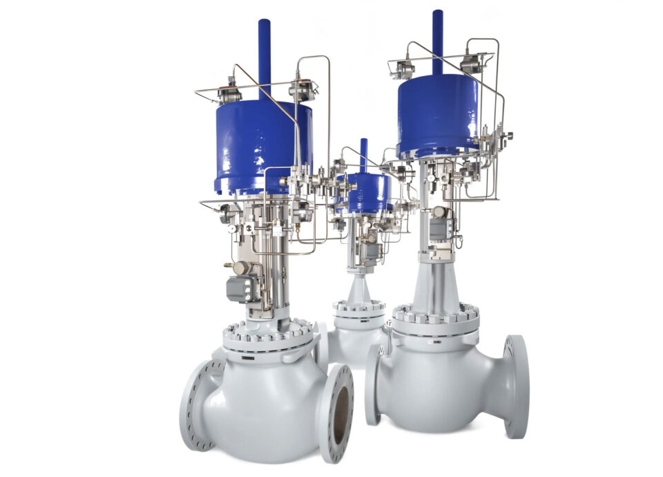
Pneumatic Actuator Valve Types
Main Types of Pneumatic Linear Actuators
Pneumatic linear actuators are primarily categorized into two main types:
- Single-Acting Actuators: These actuators feature an internal spring that returns the piston to its default position. Compressed air is only used to move the piston in one direction (e.g., to open the valve). When the air supply is cut, the spring automatically pushes the piston back, closing the valve. This fail-safe mechanism is crucial for safety applications where a default position is required during power or air loss. They are less complex and generally more cost-effective for applications requiring a specific fail-safe action. For example, a single-acting actuator might be chosen for emergency shutdown valves.
- Double-Acting Actuators: Unlike single-acting models, double-acting actuators use compressed air to move the piston in both directions. Air is supplied to one side of the piston to extend it, and to the other side to retract it. This provides precise control over both opening and closing actions and is ideal for applications where rapid and controlled movement in both directions is necessary, without a pre-defined fail-safe position. They are typically more compact for a given force output as they don’t house a large return spring.
Differences Between Linear and Rotary Pneumatic Actuators
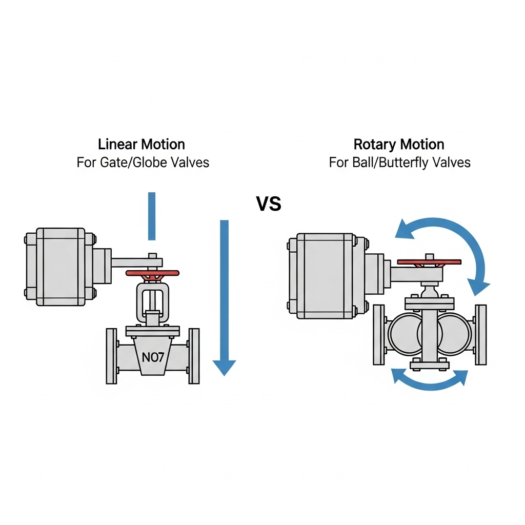
While both linear and rotary pneumatic actuators leverage compressed air, their fundamental difference lies in the type of motion they produce:
| Feature |
Linear Pneumatic Actuator |
Rotary Pneumatic Actuator |
| Motion Type |
Straight-line, push-pull motion (e.g., for gate or globe valves) |
Rotational motion (e.g., for ball, butterfly, or plug valves) |
| Valve Types |
Gate valves, Globe valves, Diaphragm valves |
Ball valves, Butterfly valves, Plug valves |
| Control |
Precise positioning for flow regulation |
Usually 90-degree or 180-degree rotation for on/off or diversion |
| Mechanism |
Piston or diaphragm moving within a cylinder |
Rack and pinion, scotch yoke, or vane designs |
| Typical Force |
High thrust capabilities (e.g., up to 200 kN for large industrial valves) |
High torque capabilities (e.g., up to 10,000 Nm for large quarter-turn valves) |
| Complexity |
Generally simpler mechanical design |
Can involve more complex gearing for torque multiplication |
Choosing between a linear and rotary actuator fundamentally depends on the type of valve being operated and the required motion. For instance, a gate valve requires a linear push-pull action to open or close, making a linear actuator the only viable choice. Conversely, a ball valve rotates to control flow, necessitating a rotary actuator.
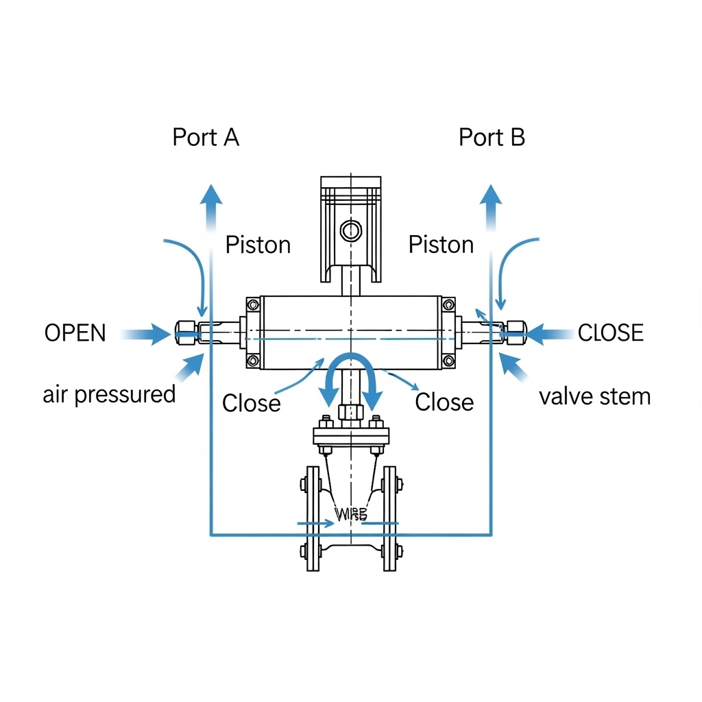
Pneumatic Actuator Valve Diagram
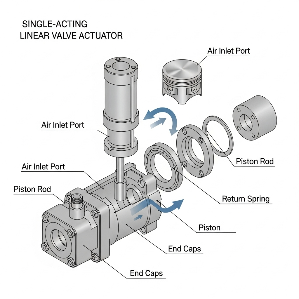
Key Parts of a Pneumatic Linear Valve Actuator
Understanding the internal components of a pneumatic linear valve actuator is crucial for proper installation, maintenance, and troubleshooting. Here are the key parts:
- Cylinder: The main body that houses the piston or diaphragm. It’s designed to withstand the internal air pressure and guide the linear movement.
- Piston/Diaphragm: The element that moves inside the cylinder in response to air pressure. A piston is rigid, while a diaphragm is flexible. Diaphragm actuators are often preferred for their sensitivity and lack of sliding seals, reducing friction.
- Piston Rod/Stem: Connects the piston to the valve stem, transmitting the linear force to actuate the valve.
- Spring (for Single-Acting): Provides the force to return the actuator to its default position when air pressure is released. These are typically heavy-duty coil springs designed for millions of cycles.
- Ports: Inlet and outlet connections for compressed air. Dual ports are common for double-acting actuators, while single-acting actuators typically have one active port.
- Seals/O-rings: Crucial for maintaining air pressure within the cylinder and preventing leakage. Their material must be compatible with the operating temperature and environment.
- End Caps: Seal the ends of the cylinder and often house the spring or mounting points.
Understanding Pneumatic Linear Valve Actuator Parts and Diagram
Imagine a basic pneumatic linear actuator as a robust cylinder with a piston inside. When compressed air enters one side of the piston, it pushes the piston forward. If it’s a single-acting unit, a spring on the other side compresses, ready to push the piston back when the air is released. For a double-acting unit, air would then be directed to the other side to move the piston in the opposite direction. This linear motion of the piston is then transferred via a connecting rod directly to the stem of the valve. For example, in a globe valve, the actuator’s stem is directly coupled to the valve’s stem. As the actuator stem extends, it pushes the valve plug down onto the seat, closing the valve. When the actuator stem retracts, it lifts the plug off the seat, opening the valve. The precision of this movement dictates the flow control capabilities of the entire system.
A simple diagram depicting a single-acting and double-acting pneumatic linear actuator with labeled parts would significantly enhance this section’s clarity and understanding for the reader
Pneumatic Linear Valve Actuator Price
What Affects Pneumatic Linear Valve Actuator Cost?
The cost of a pneumatic linear valve actuator can vary significantly, ranging from hundreds to tens of thousands of dollars, primarily depending on several critical factors:
- Size and Force Output: Larger actuators capable of generating higher thrust (e.g., over 50 kN) for large-bore valves will naturally be more expensive due to material consumption and manufacturing complexity. A 4-inch (DN100) actuator might cost significantly less than a 24-inch (DN600) model designed for high-pressure service.
- Material Construction: Standard aluminum or stainless steel bodies are common, but for corrosive or high-temperature environments (e.g., acidic chemical plants, steam lines up to 250°C), specialized alloys like Hastelloy or Monel can dramatically increase the price, sometimes by 50-100%.
- Accessories and Instrumentation: Adding positioners (for modulating control), limit switches (for open/closed feedback), solenoid valves, air filters, and quick exhaust valves can increase the total cost by 20-50%. A smart positioner with HART communication can add $500-$1500 to the base price.
- Certifications and Ratings: Actuators required for hazardous areas (e.g., ATEX, UL, IECEx for Zone 1 or Zone 2 classifications) or specific industry standards (e.g., API 6A for oilfield equipment) will have higher costs due to stringent testing and compliance requirements.
- Brand and Manufacturer: Established brands with long reputations for reliability and after-sales support typically command a premium. However, newer or regional manufacturers might offer more competitive pricing without sacrificing quality. For example, VALVEHU, a China-based valve manufacturer trusted by engineers worldwide, delivers precision-engineered flow control solutions at competitive prices for industrial buyers.
Price Comparison for Industrial Buyers
For industrial buyers, a comprehensive price comparison goes beyond the initial purchase cost. Consider these aspects:
| Factor |
Low-Cost Actuator |
Mid-Range Actuator |
Premium Actuator |
| Initial Cost |
$150 – $800 (for smaller, standard applications) |
$800 – $5,000 (standard industrial, moderate sizing) |
$5,000 – $25,000+ (large, specialized, high-performance) |
| Materials |
Standard aluminum, basic coatings |
Aluminum, epoxy coating, stainless steel trim |
Stainless steel, exotic alloys (e.g., Duplex, Super Duplex) |
| Lifespan |
1-3 million cycles (estimated) |
3-5 million cycles (estimated) |
5-10+ million cycles (estimated) |
| Maintenance |
Potentially higher frequency of seal/component replacement |
Standard maintenance intervals |
Lower maintenance, longer intervals |
| Warranty |
6 months to 1 year |
1-2 years |
2-5 years |
| Availability |
Often readily available |
Good stock levels for common sizes |
May require custom manufacturing with lead times of 8-16 weeks |
| Total Cost of Ownership |
Can be higher due to increased downtime and replacement costs |
Balanced TCO, good performance for most applications |
Lower TCO in critical applications due to reliability and longevity |
For instance, purchasing a low-cost actuator for a critical steam application might save 20% upfront but could lead to 30% higher operational costs over 5 years due to premature failure and associated downtime. Always balance the initial investment with long-term reliability and operational expenses.
Pneumatic Linear Valve Actuator Manufacturers
Top Pneumatic Linear Valve Actuator Manufacturers in 2025
The market for pneumatic linear valve actuators is robust, with several key players known for their quality, innovation, and global presence. As of 2025, some of the top manufacturers include:
- Emerson (Fisher, Bettis): A global leader offering a comprehensive range of actuators and control solutions, known for robust designs and advanced instrumentation. Their Fisher DVC series is a benchmark in intelligent valve control.
- Rotork: Renowned for high-performance fluid power solutions, including heavy-duty linear actuators for demanding applications like power generation and water treatment.
- IMI Critical Engineering (IMI Norgren): Offers a wide array of pneumatic components, including reliable linear actuators, often integrated into their broader flow control systems.
- Auma: While primarily known for electric actuators, Auma also produces robust pneumatic linear actuators, particularly for large, high-thrust applications.
- Flowserve: A major player in the pump, valve, and seal industry, Flowserve provides a diverse portfolio of actuators, including robust linear pneumatic options.
- VALVEHU: As a leading valve manufacturer and supplier in China, VALVEHU has rapidly gained recognition for its cost-effective yet high-quality pneumatic linear actuators, often serving as a reliable alternative for industrial buyers seeking competitive pricing without compromising on performance for standard industrial applications. They offer various customizable options to meet specific project needs.
How to Choose the Right Manufacturer
Selecting the right manufacturer is paramount for long-term operational success and cost-efficiency. Here’s a pragmatic approach:
- Application Requirements: Does the manufacturer offer actuators specifically designed for your industry (e.g., food grade, cryogenic, high-pressure)? Check their product datasheets for compatibility with your operating conditions (pressure, temperature, media).
- Product Range and Customization: Does their portfolio cover the sizes, materials, and force outputs you need? Can they provide custom solutions if your application has unique requirements, such as extended stroke lengths or specialized coatings?
- Quality and Reliability: Look for certifications (ISO 9001, ATEX, SIL ratings). Research their track record. Online reviews and industry forums can provide insights into real-world performance and longevity. A good manufacturer will provide clear MTBF (Mean Time Between Failures) data if requested.
- Technical Support and Service: Evaluate their pre-sales technical assistance and after-sales support. Do they offer local service, spare parts availability, and troubleshooting guides?
- Cost and Lead Time: Obtain multiple quotes. Compare not just the price but also the lead time, shipping costs, and payment terms. A longer lead time could mean significant project delays.
- Brand Reputation vs. Value: While established brands offer peace of mind, companies like VALVEHU provide excellent value, especially for projects with budget constraints, without compromising on essential performance metrics. Evaluate if their standard offerings meet your core requirements.
Installation and Troubleshooting
Pneumatic Linear Valve Actuator Installation Guide
Proper installation is critical for the long-term performance and reliability of any pneumatic linear valve actuator. Follow these general steps:
- Safety First: Always depressurize the air supply system and lockout/tagout the power before beginning installation. Wear appropriate PPE.
- Mounting Compatibility: Ensure the actuator’s mounting flange (e.g., ISO 5210 for rising stem valves) perfectly matches the valve’s mounting surface. Any misalignment can lead to stem binding and premature failure.
- Stem Connection: Connect the actuator stem to the valve stem securely. Use appropriate couplings and ensure the correct stroke length is set. A common issue is incorrect stroke adjustment, leading to incomplete valve closure or opening.
- Air Supply Connection: Connect clean, dry, instrument-grade compressed air (typically 80-120 psi or 5.5-8.3 bar) to the actuator’s ports. Use appropriate fittings and ensure all connections are leak-free.
- Accessory Installation: Install any accessories like positioners, solenoid valves, or limit switches according to the manufacturer’s instructions. Calibrate positioners as per the vendor’s manual.
- Functionality Test: Before commissioning, perform a full open/close cycle test with air pressure to verify smooth operation and correct stroke. Check for any air leaks.
- Environmental Considerations: Ensure the actuator is protected from extreme temperatures, corrosive atmospheres, and excessive vibration, which can shorten its lifespan. Consider protective enclosures if necessary.
Common Pneumatic Linear Valve Actuator Troubleshooting Tips
Even with proper installation, issues can arise. Here are common troubleshooting tips:
- Actuator Not Moving/Slow Response:
- Check Air Supply: Verify adequate air pressure (typically 80-120 psi) at the actuator inlet. Clogged air filters or undersized supply lines (less than 1/4 inch NPT for small actuators) can restrict flow.
- Solenoid Valve Malfunction: Test the solenoid valve. It might be stuck or receiving no electrical signal. Use a multimeter to check for voltage.
- Internal Leaks: Listen for air leaks around the cylinder seals or piston rod. Minor leaks can lead to sluggish operation. Replace seals if necessary.
- Valve Stem Sticking: Disconnect the actuator and manually try to operate the valve. If the valve stem is seized or stiff, the problem might be with the valve, not the actuator.
- Incomplete Stroke:
- Insufficient Air Pressure/Volume: The actuator might not be receiving enough force to complete the full stroke, especially if operating against high differential pressure.
- Incorrect Stroke Adjustment: Re-adjust the stroke length as per the valve’s requirements.
- Obstruction: Check for any physical obstruction preventing full movement of the valve stem.
- Air Leakage:
- External Leaks: Check all fittings and connections with soapy water. Tighten or replace fittings as needed.
- Internal Leaks (Piston Seal): If air continuously vents from one port while pressure is applied to the other (in double-acting units), the piston seals might be worn. This requires disassembly and seal replacement.
Warning: Always depressurize the actuator and lockout/tagout the energy source before attempting any internal repairs. Working with pressurized systems can be extremely dangerous, potentially causing severe injury or death. Consult the manufacturer’s manual for specific troubleshooting steps and safety precautions for your particular model.
Best Pneumatic Linear Valve Actuator for Industrial Use
How to Select the Best Pneumatic Linear Valve Actuator
Choosing the “best” pneumatic linear valve actuator isn’t about finding a single universal product, but rather identifying the optimal fit for your specific industrial application. Here’s a structured approach:
- Determine Valve Requirements:
- Valve Type: Is it a gate, globe, diaphragm, or pinch valve? This dictates the linear motion required.
- Thrust Requirements: Calculate the force (in pounds-force or Newtons) needed to open and close the valve against maximum process differential pressure. Valve manufacturers usually provide this data. A common safety factor of 1.5x to 2x the calculated thrust is recommended.
- Stroke Length: Measure the full travel distance of the valve stem from fully closed to fully open.
- Operating Pressure & Temperature: Ensure the actuator’s materials and seals can withstand the process media’s temperature range (e.g., -20°C to +80°C for standard NBR seals).
- Define Actuator Characteristics:
- Single-Acting vs. Double-Acting: Does your application require a fail-safe position? If so, specify “Fail-Open” or “Fail-Close” and choose a single-acting actuator. If not, a double-acting actuator offers more flexible control.
- Air Supply Availability: What is the maximum and minimum instrument air pressure available? Actuators are typically designed for 80-120 psi (5.5-8.3 bar).
- Cycle Speed: How fast does the valve need to open/close? This influences cylinder size and the need for quick exhaust valves. For example, emergency shutdown (ESD) valves might require closure in less than 2 seconds.
- Duty Cycle: How frequently will the actuator operate? For high-cycle applications (e.g., thousands of cycles per day), choose heavy-duty models with robust internal components and superior seals.
- Consider Environmental Factors:
- Corrosion: Is the environment corrosive (e.g., offshore platforms, chemical plants)? Specify stainless steel construction or corrosion-resistant coatings.
- Hazardous Areas: If operating in potentially explosive atmospheres, ensure the actuator is certified (e.g., ATEX, IECEx) for the specific zone classification (Zone 0, 1, or 2).
- Vibration/Shock: For applications with high vibration, ensure the mounting hardware and internal components are robust enough to prevent loosening or damage.
- Integrate Control Systems:
- Positioners: For modulating control (proportional flow), a pneumatic or electro-pneumatic positioner is essential.
- Limit Switches: To provide feedback on valve position (open/closed), choose actuators with compatible mounting for limit switches (e.g., NAMUR standard).
- Solenoid Valves: For on/off control, a solenoid valve is needed to direct air pressure to the actuator.
By systematically addressing these points, you can narrow down options and select a pneumatic linear valve actuator that not only meets your technical specifications but also provides long-term reliability and cost-effectiveness for your industrial operations.
Final Thoughts on Pneumatic Linear Valve Actuators
Pneumatic linear valve actuators are indispensable workhorses in industrial automation, offering a robust, reliable, and inherently safe means of controlling critical fluid flows. Their widespread adoption is a testament to their simplicity of design, ease of maintenance, and the direct conversion of air pressure into powerful linear motion. While selecting the ideal actuator requires careful consideration of thrust requirements, environmental conditions, and control needs, the return on investment in terms of process efficiency and safety is substantial. As industrial processes become increasingly automated and precise, the role of these actuators will only continue to grow. Understanding their working principles, various types, and proper installation practices is fundamental for engineers and plant operators aiming for optimal performance and minimizing downtime.